nossa!! achei na net!!! se alguem se abilita. depois mostra pra gente
Hey guys,
Here's that tutorial on scratchbuilding disc brakes.....
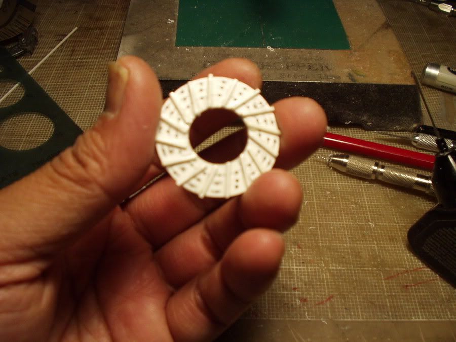
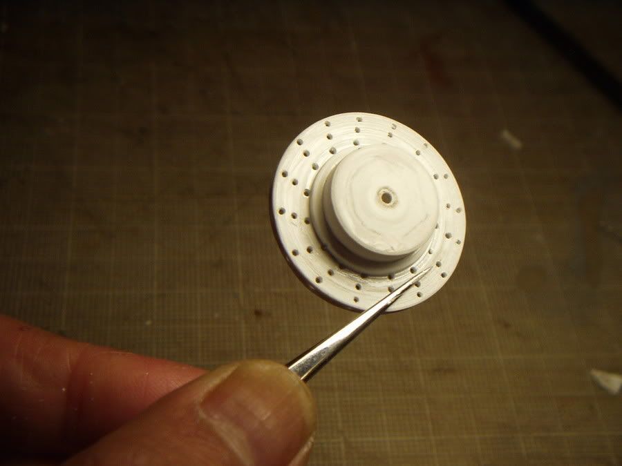
These steps show a simple 13" brake disc that's cross drilled and ventilated. You can modify the procedures and apply them to any size that you might require for your application.
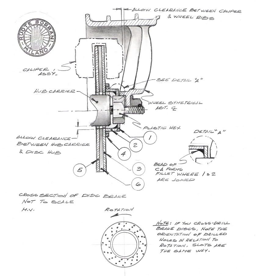
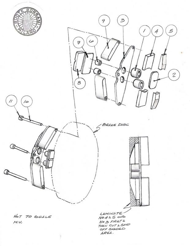
I've provided a rough sketch to assist in identifying part number call-outs.
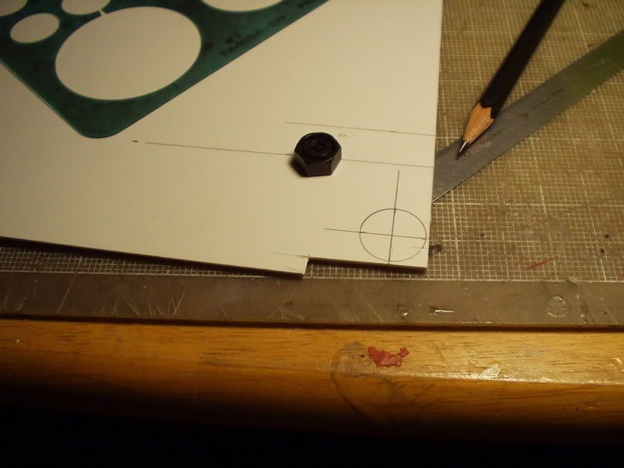
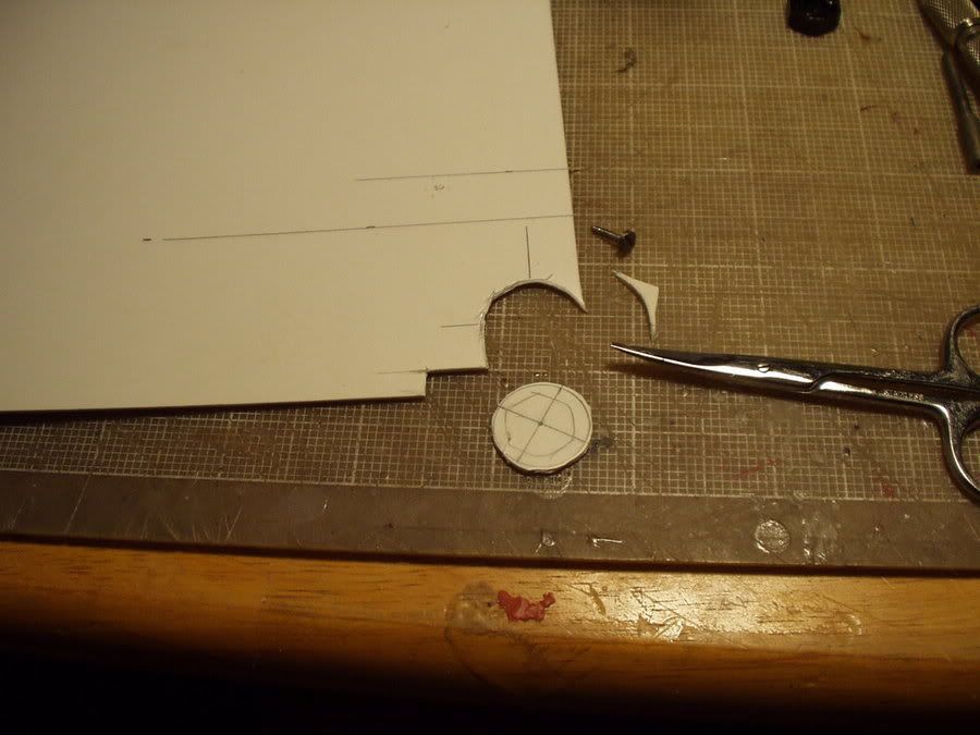
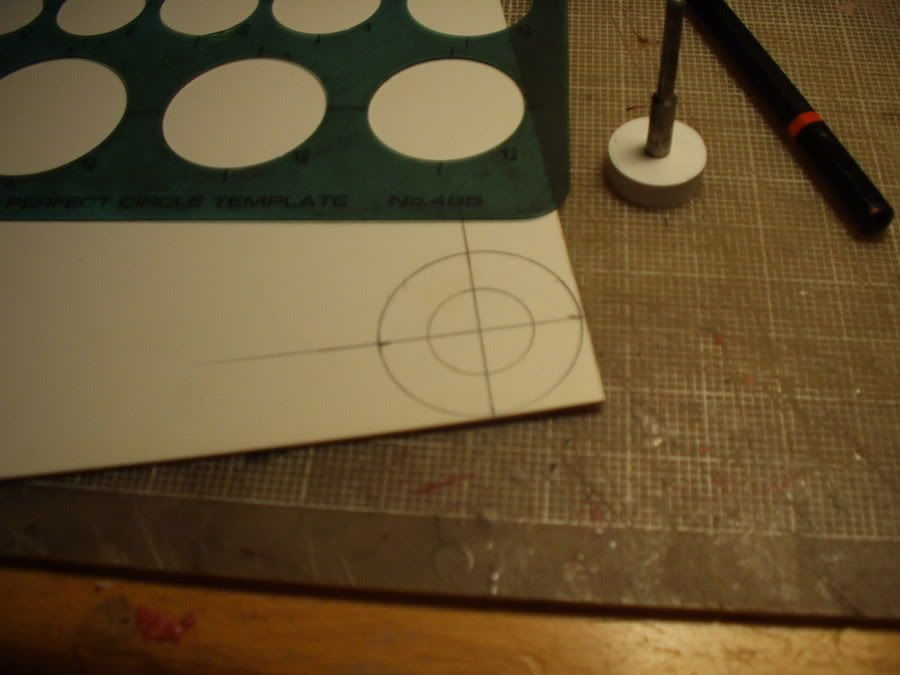
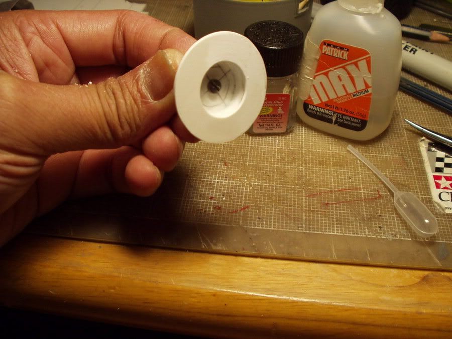
step 1
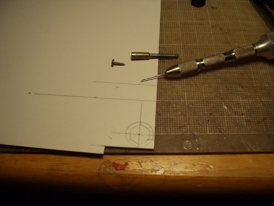
step 2
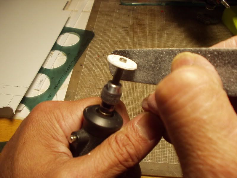
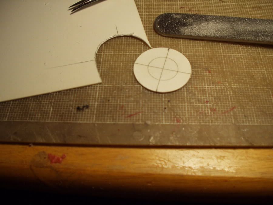
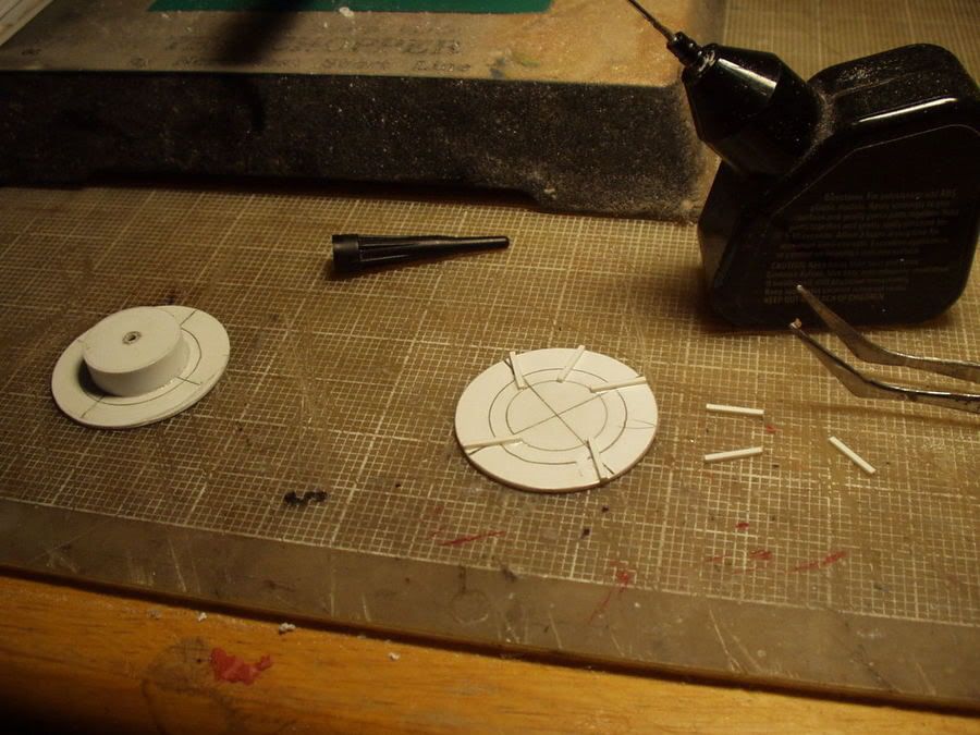
step 3
step 4
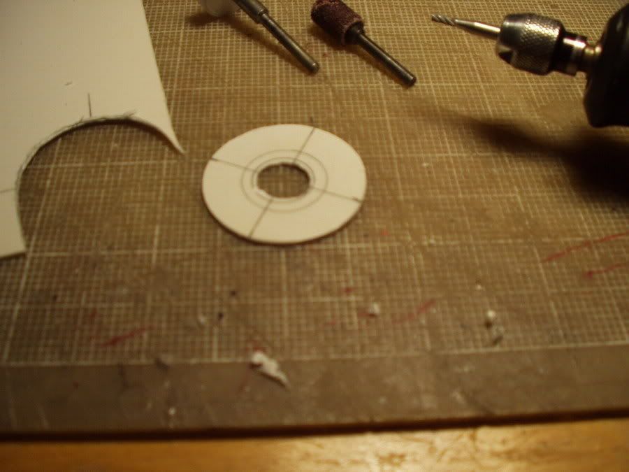
step 5
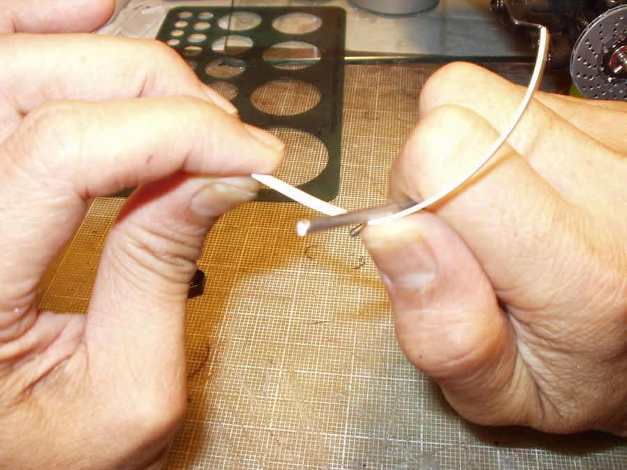
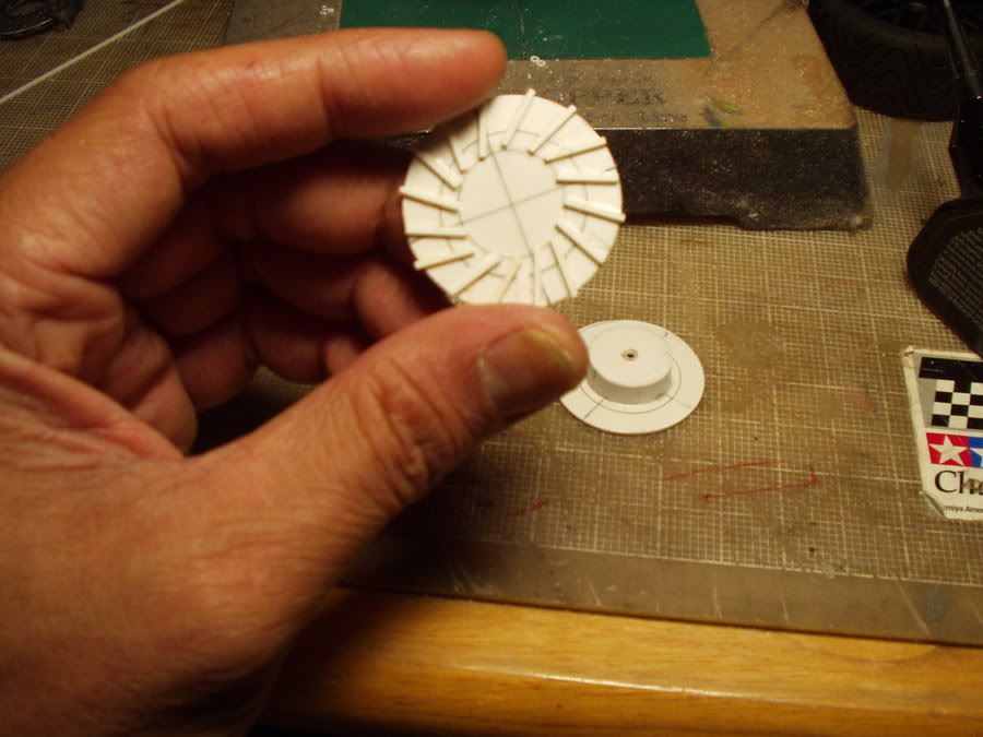
step 6
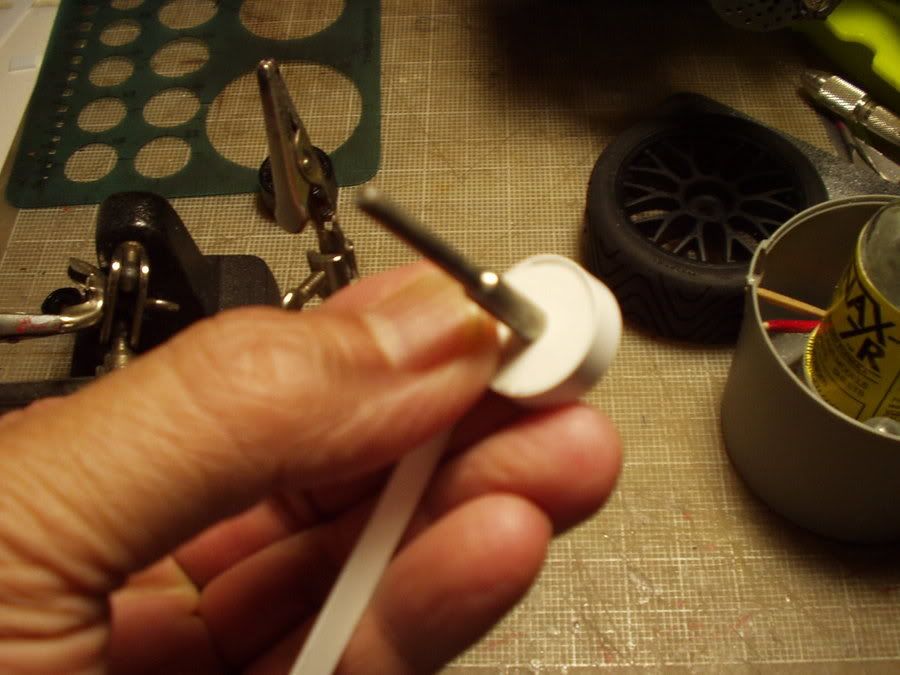
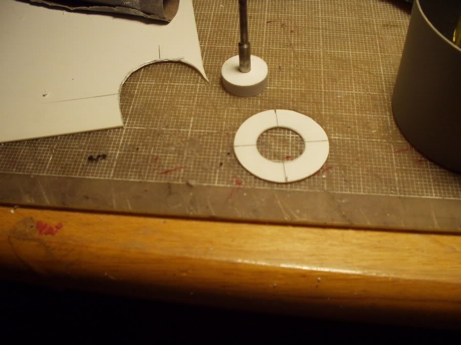
step 7
step 8
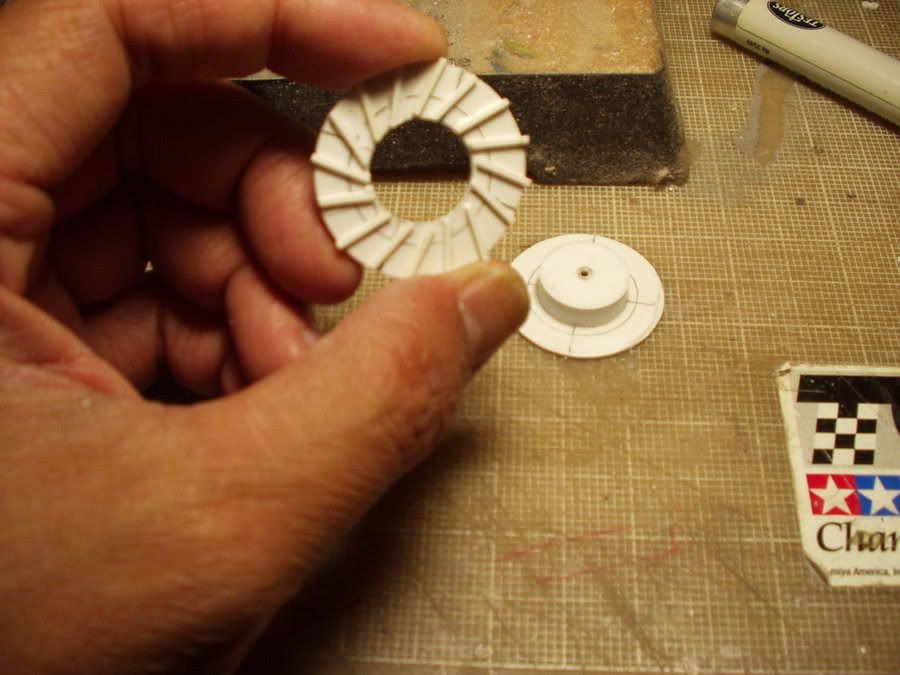
step 9
step 10
step 11
step 12
step 13
step 14
step 15
step 16
step 17
step 18
step 19
Part 2
Here's an exploded assembly sketch:
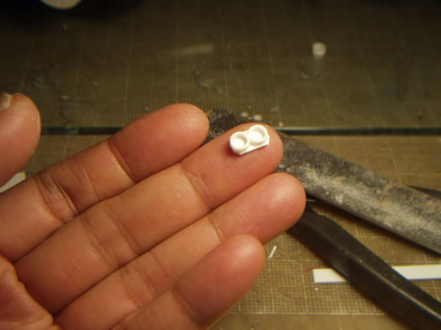
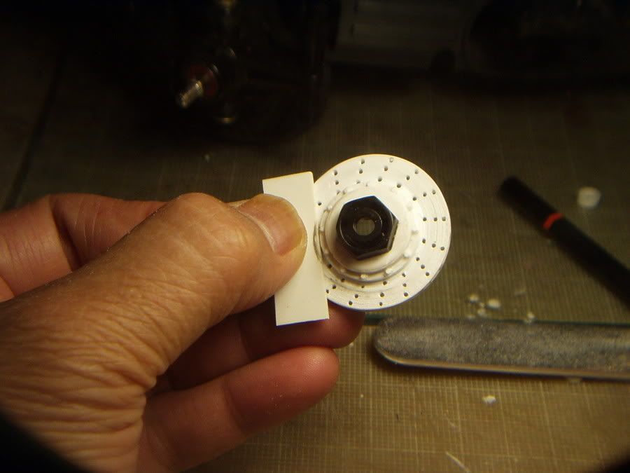
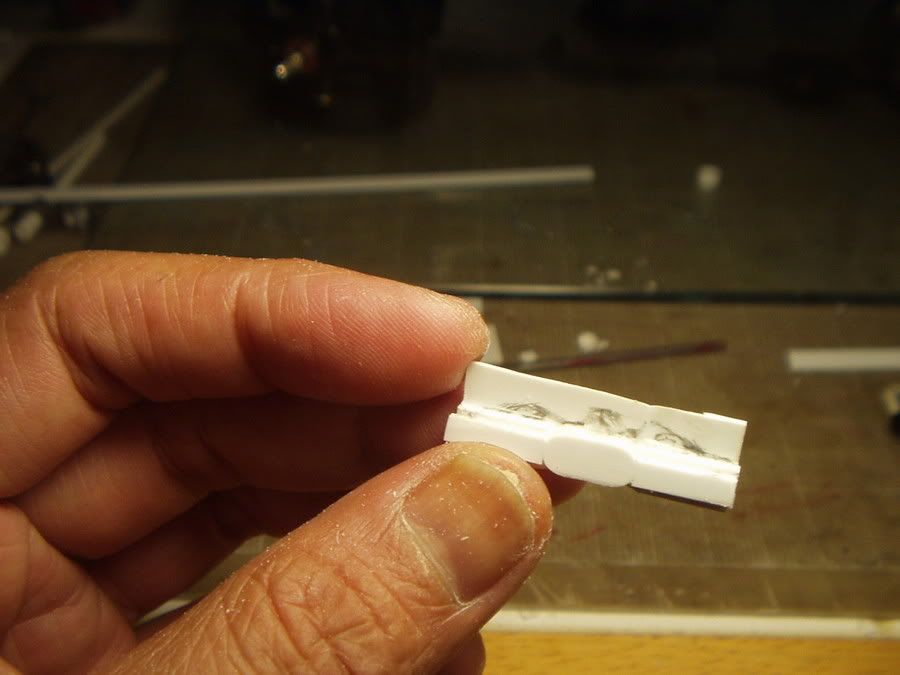
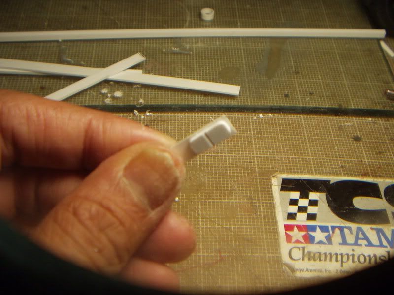
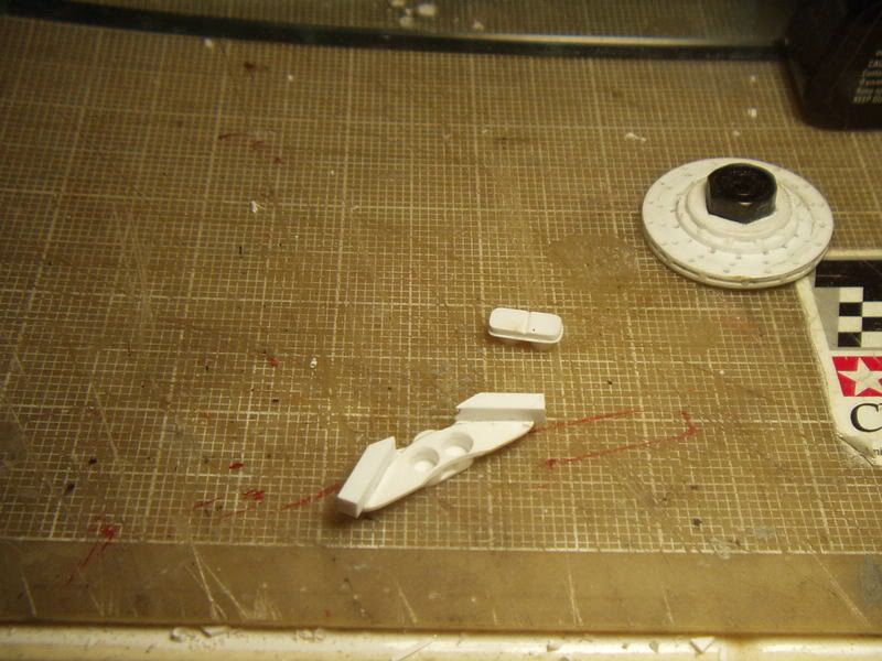
1) To make the wheel cylinders (Part no.1), I cut 2 pieces of 7/32" dia. Evergreen tubing which were then sanded to a uniform lenght of .060. I then glued both pieces onto a lenght of .040" x .188" Evergreen strip (Part no.2).
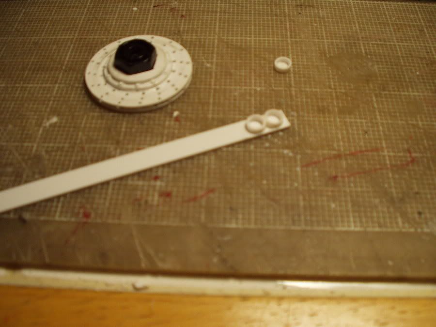
2) After the glued joint has set, I trimmed off the excess strip and sanded Part no.2 to conform to the shape of the siamesed cylinders. (see photo in step 5)
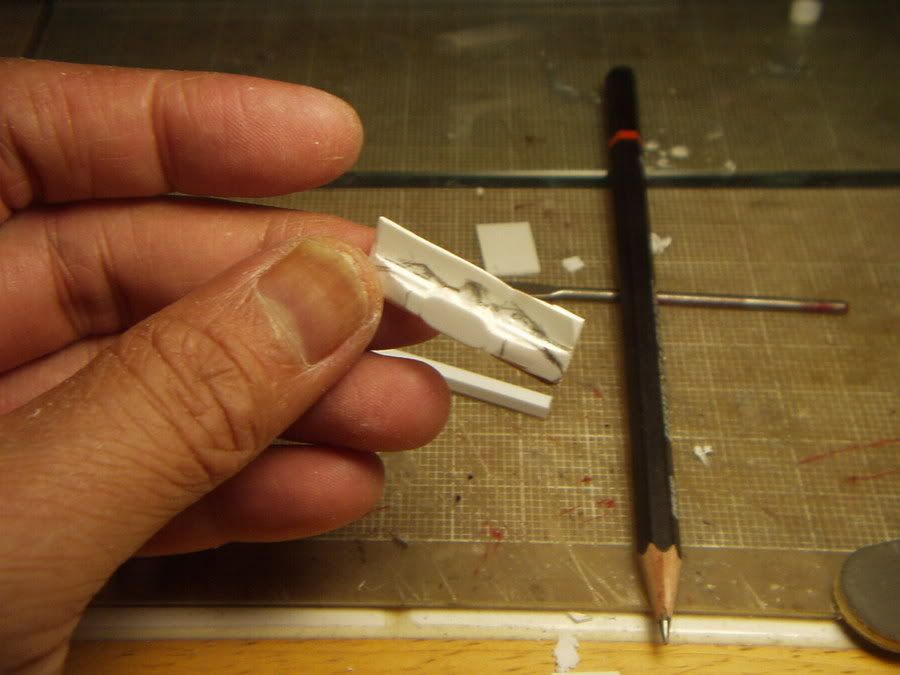
3) I used a scrap piece of .040" thk.x 1.38" x .50" Evergreen to make Part no.3.
4)
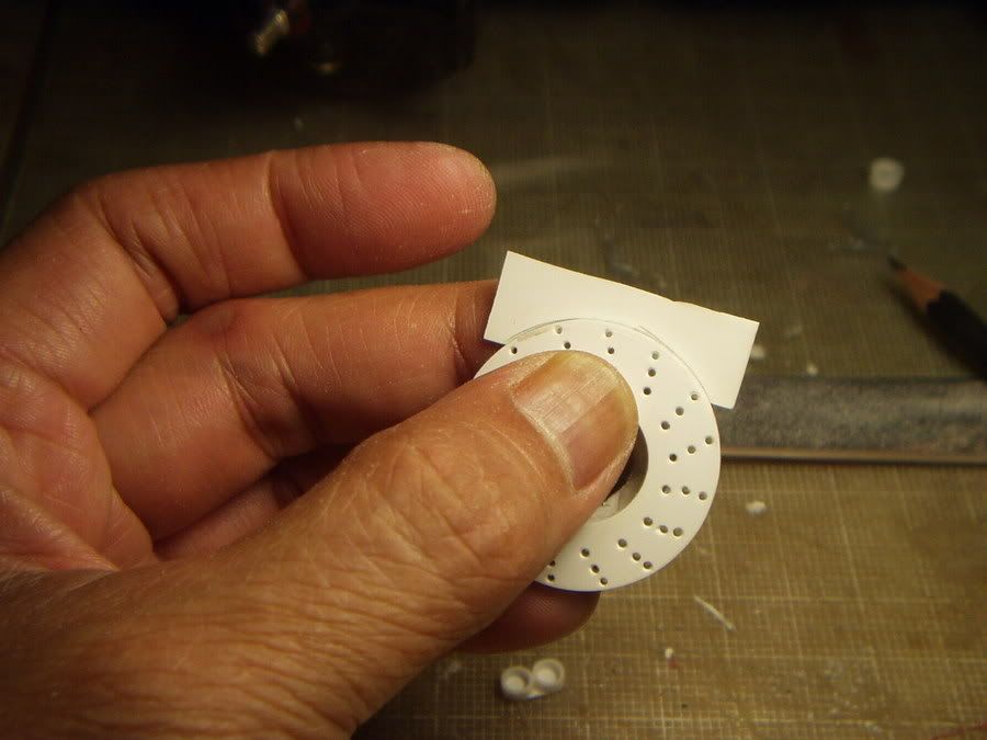
5) I glued the cylinders onto the scrap piece and marked out the design.
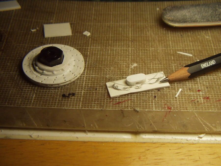
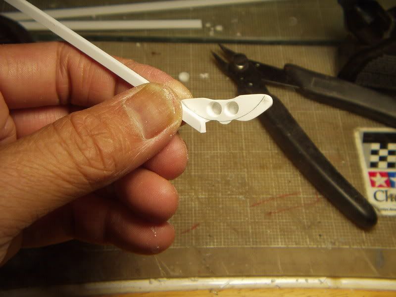
6) I glued pieces of .060" x .188" strips (Part no. 4). Note the bias-cut end where the strip joins the wheel cylinders.

I glued pieces of .060" x .125" strips (Part no. 5) centered over Part no. 4.
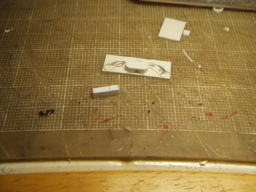
9) After the glued joints have set, I used my razor saw and file and beveled the laminations (see sketch).
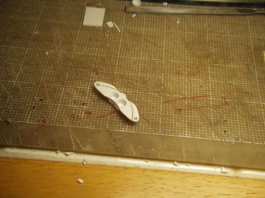
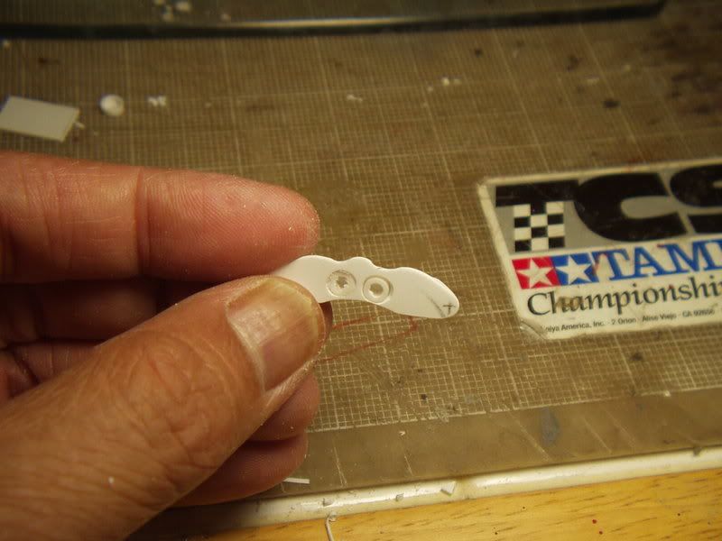
10) I trimed and filed Part no. 3 to shape. I then drilled and ground out the holes for Part no. 6. The holes are sized for the pistons to freely slide in and out. Note: You may omit this step (and Part no. 6) and simply glue the finished brake pads in place during final assembly.
11) I started the brake pads (Part no.
by beveling the ends of a lenght of .040" x .188" strip. I also added a notch as shown. Note: Check your reference photos as brake pads tend to vary greatly.
12) I trimmed Part no. 8 to lengh and glued it onto a lenght of .015" x .250 strip (Part no. 7). After the glued joint had set, I trimmed Part no. 7 to lenght and shaped the ends.
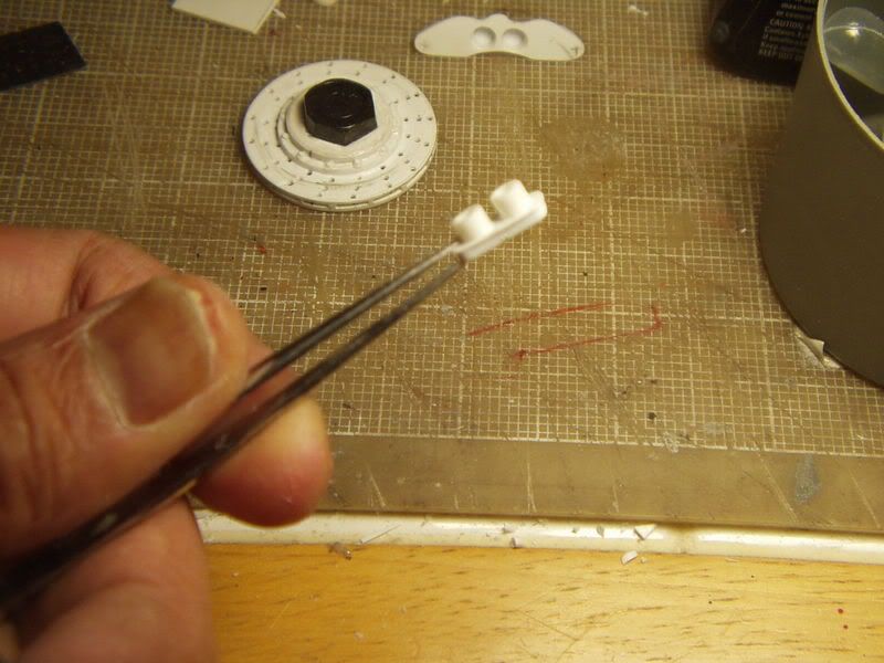
14) I used 5/32" dia. tubing to make the pistons (Part no. 6). I cut the pistons to lenght so that they sit flush inside the cylinders.
15) I glued the pistons (Part no. 6) onto the brake pads. I used slow setting liquid cement to help position the pistons so that the sub-assembly freely slides in and out of the cylinders.
16) I used lenghts of .188" x .188" strip to make Part no. 9. These were glued into place and shaped in a later step.
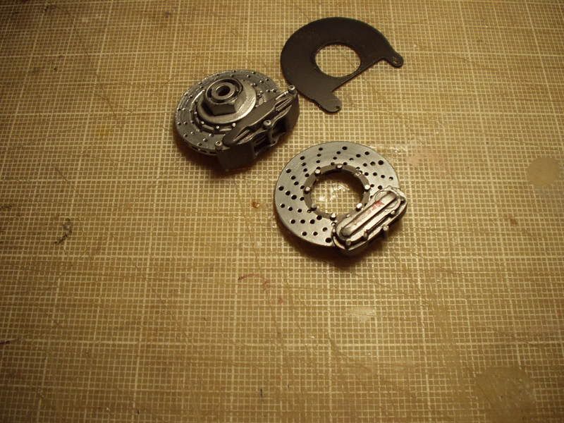
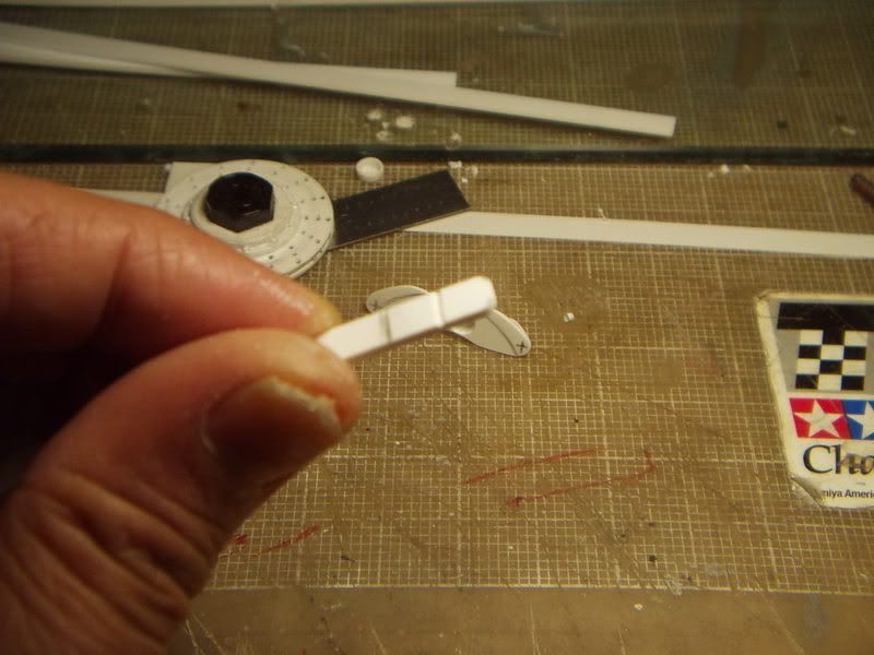
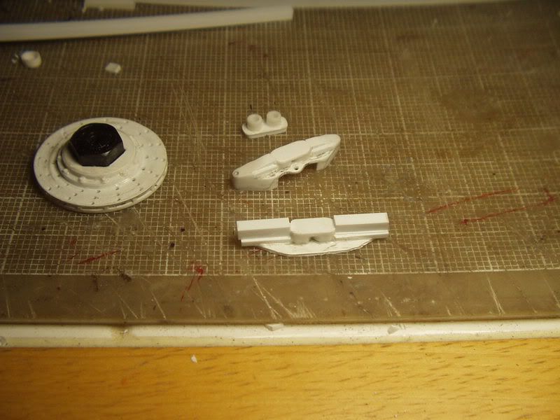
17) Here's a shot of the nearly finished caliper half and the brake pad.
18) I then sanded the caliper half to shape. I made the other caliper half using the same procedures.
19) I lined up and glued the caliper halves together.
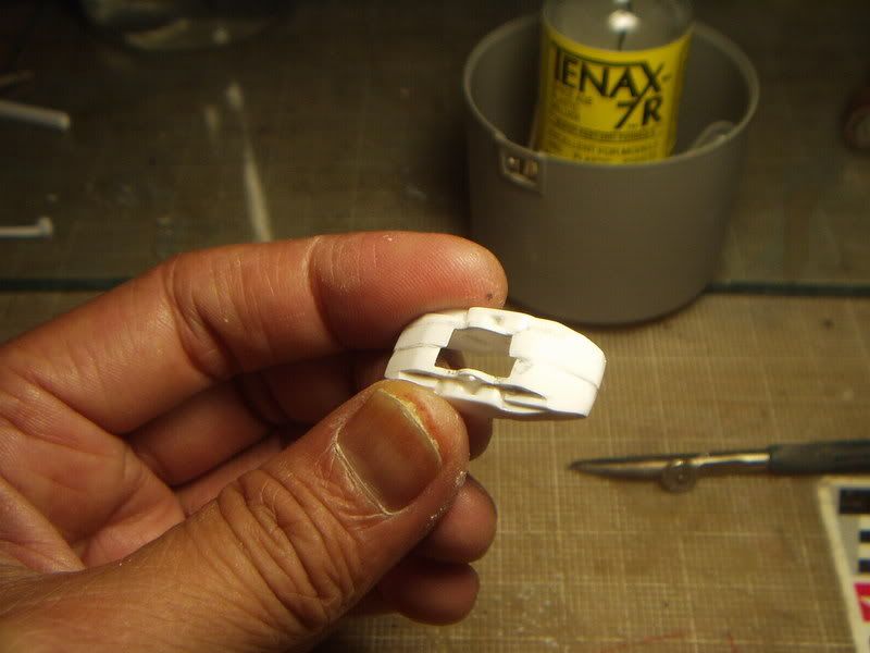
20) Because I was trying to replicate a cast one-piece caliper, I used spot putty to fill in the gaps between halves.
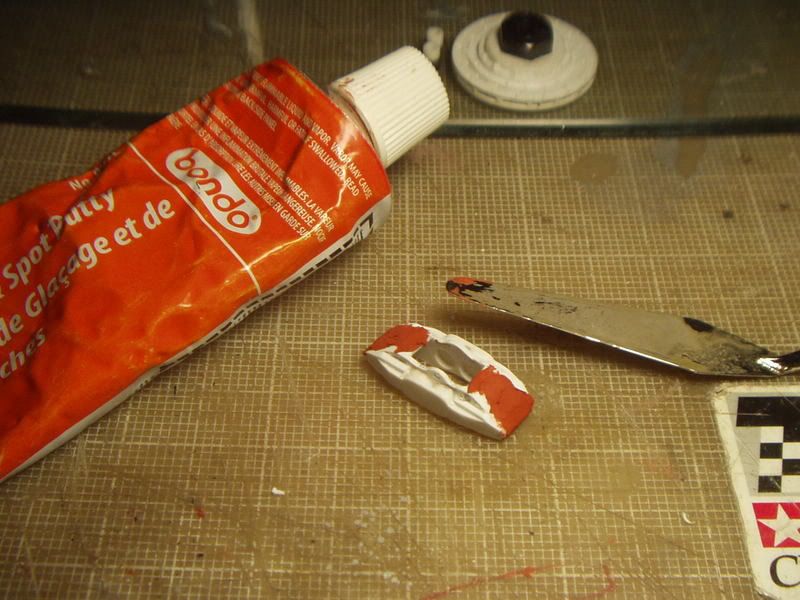
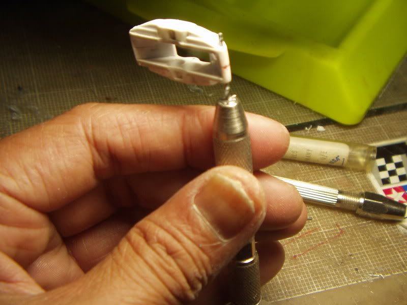
21) After sanding the filled areas, I drilled a small pilot hole through the caliper.
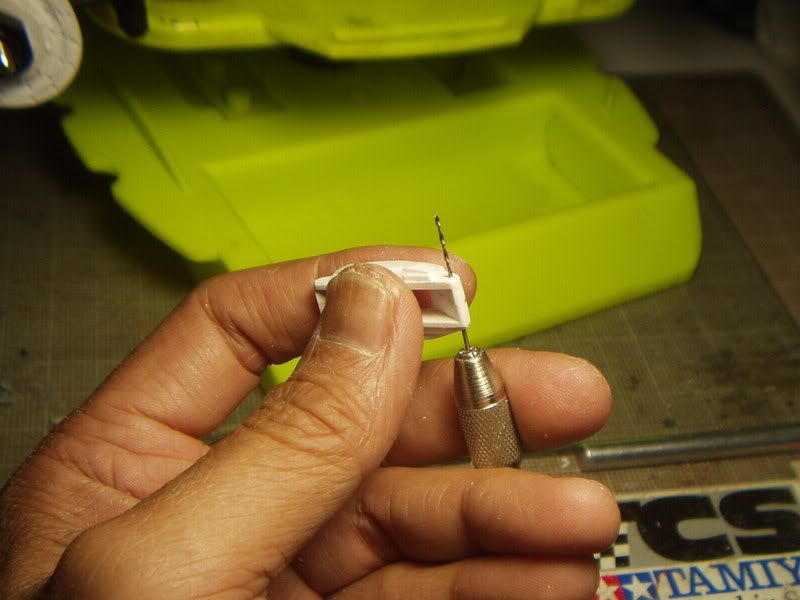
22) I then swithced to a larger bit and sized the hole for a .040" dia.plastic rod (Part no. 10).
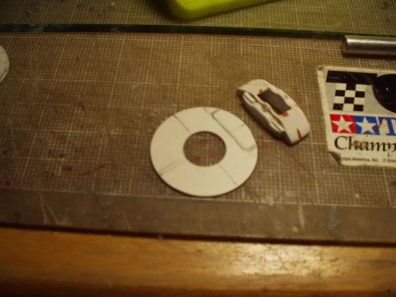
23) I marked out my backing plate onto a piece of .040" thk. sheet.
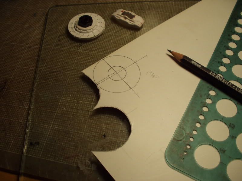
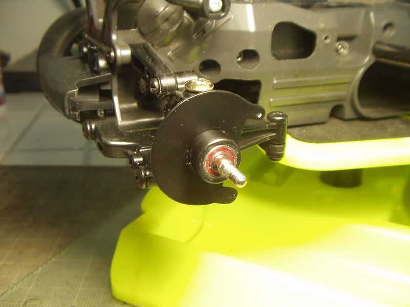
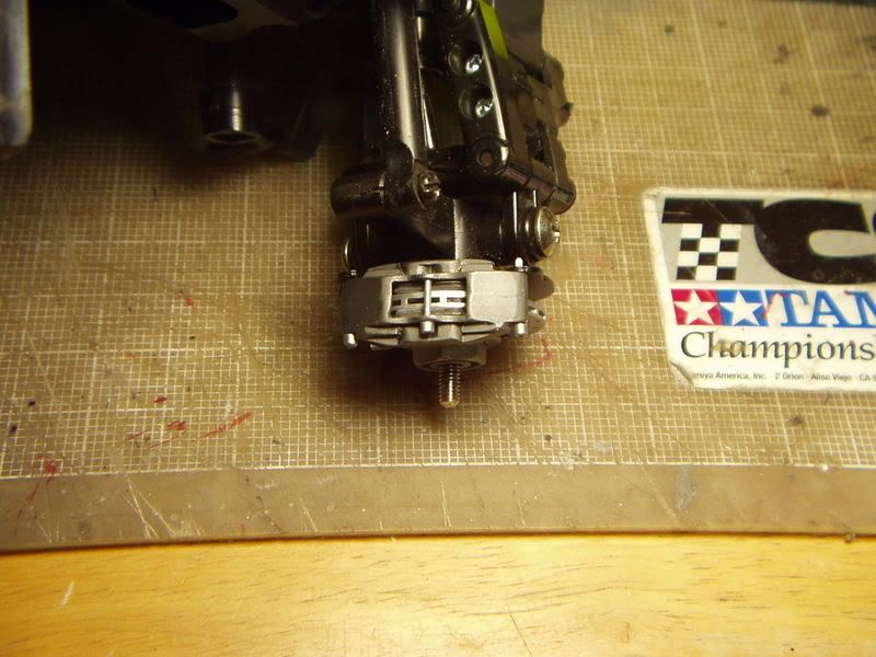
24) I cut out and sanded the backing plate to shape. The center hole is sized for a tight fit around the hub carrier on my TL-01 chassis because I wanted to be able to remove the brake assembly for racing.
25) I marked out a notch on the backing plate to clear the features on the caliper. I also filed a flate area on the caliper where it mounts onto the backing plate.
26) I had to add some scraps to the backing plate as I had miscalculated where the mounting holes would be. I drilled the holes on the backing plate using the caliper as a guide. I temporarily pinned things together with some .040" dia. rod.
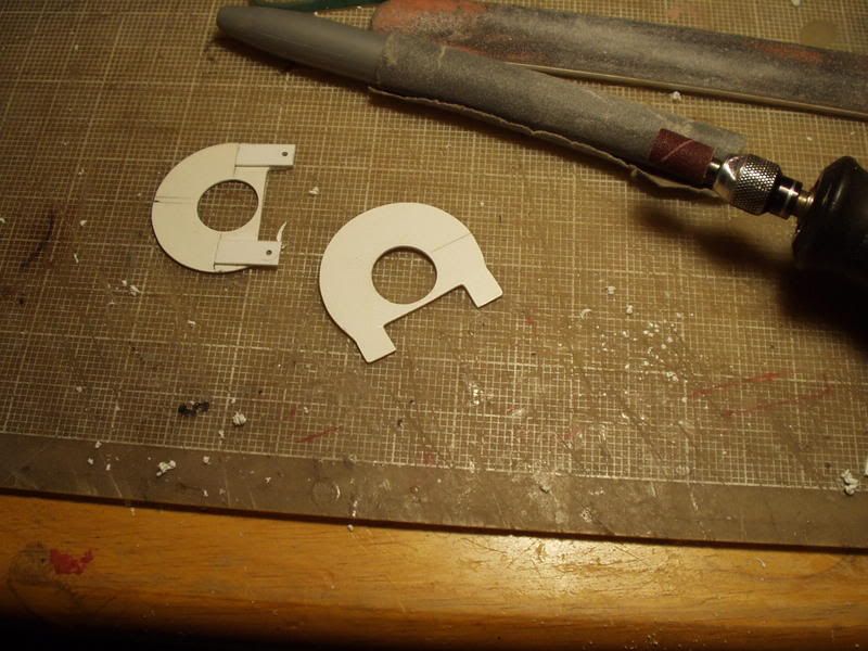
28) I transfered the correct outline of the backing plate onto another piece of .040" thk. sheet and made a new one.
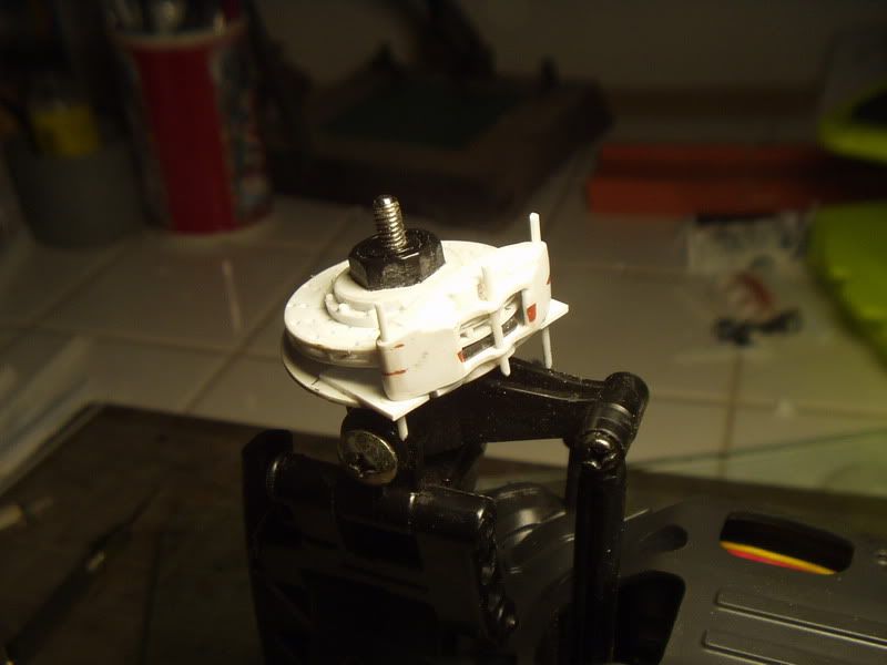
29) Drilling the new backing plate for mounting holes. I had to re-adjust so that the center fastener (Part no. 10/11) clears the brake disc.
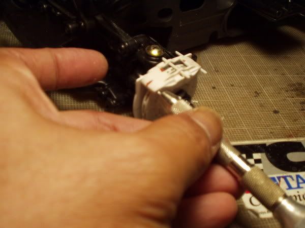
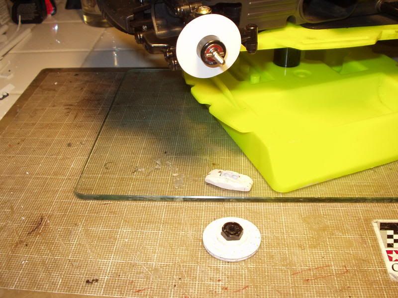
30) I had to trim the backing plate a little after I found some rubbing between it and the wheel.
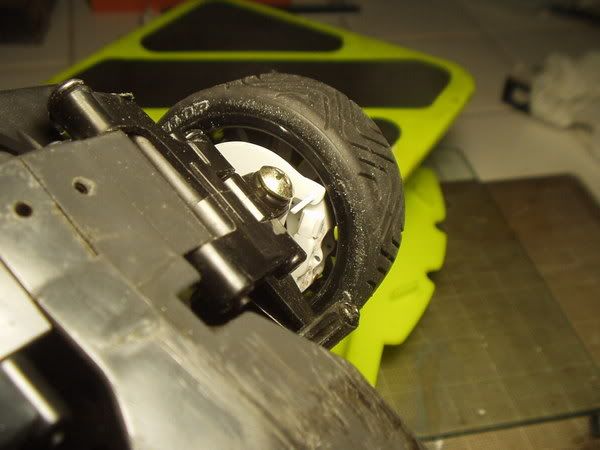
31) A final check for clearances between the caliper and the wheel spokes.
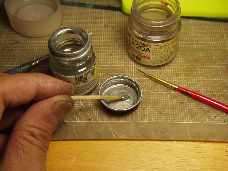
32) I washed and scrubbed the parts thoroughly with an old toothbrush prior to painting.
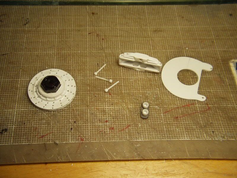
34) The backing plate was sprayed with some Plasti-Kote Bumper Paint (black).
35) The brake disc was sprayed with Metalizer Stainless Steel. After the required waiting period, I used some facial tissue and q-tips to buff out the swept areas. I left the center section umpolished and I used a little black wash around the bolt heads.
37) The caliper assembly was sprayed with Metalizer Gunmetal (mixed with a little flat black) and left unpolished. The fasteners (Part nos. 10 & 11) were made using lenghts of .040" dia. rod and 3/32" dia. tubing. The fasteners were painted Metalizer Stainless Steel and buffed. The brake pads were painted with Metalizer GunMetal. After the painted parts have dried, I simply popped in the brake pads and pinned everything together using the fasteners. The center fastener was glued in place.
38)
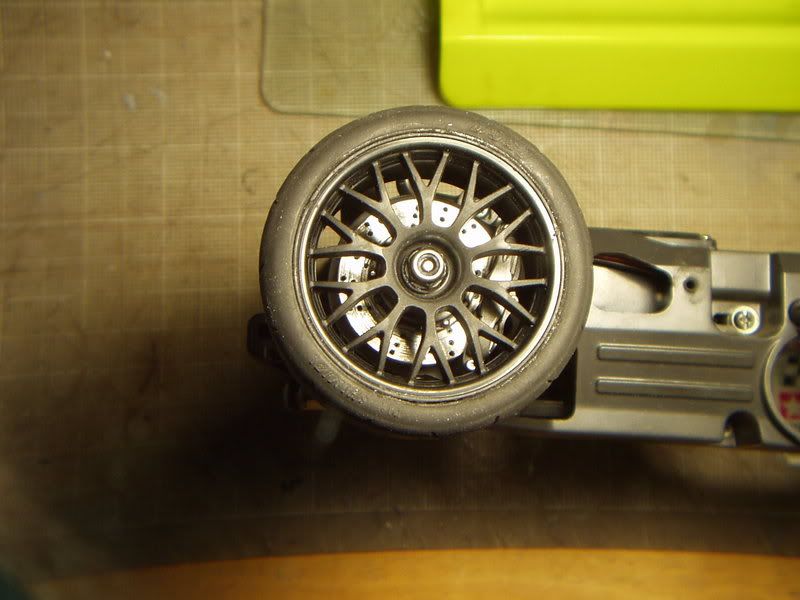
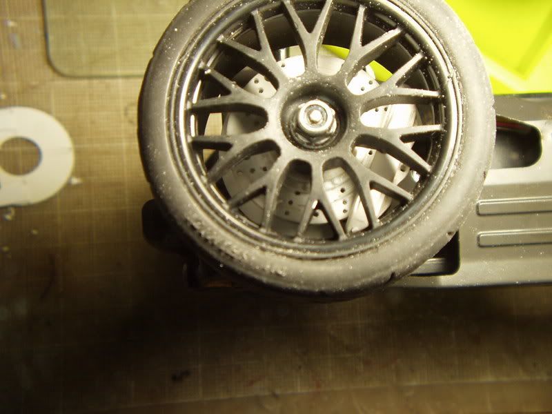
39) The new disc brake looks a heck of a lot better than a very early (and crude) set that I had made a few years ago.